OCR A Physics OCR Paper 3 2024

-
Section A
-
You should spend a maximum of 30 minutes on this section.
-
Write your answer to each question in the box provided.
- 1. What are the base units of a kilowatt-hour?
- A. [math]J[/math]
- B. [math]kg\ m^{2}\ s^{-1}[/math]
- C. [math]kg\ m^{2}\ s^{-2}[/math]
- D. [math]W\ s[/math]
- Answer: C
- Explain:
- – A kilowatt hour (kW) is a unit of energy.
- – Energy is measured in Joules (J), where [math]1\ J = 1N.m[/math].
- – Expressing force (N) in SI base units: [math]N = kg\ m\ s^{-2}[/math].
- – Therefore, energy in SI base units is:
- [math]Base\ units = kg\ m\ s^{-2} \times m[/math]
- [math]= kg\ m^{2}s^{-2}[/math]
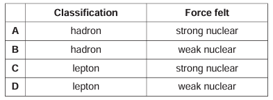
- 2. A neutrino is a fundamental particle. Which row of the table correctly describes a neutrino?
- Answer: D
- Explain:
- – Neutrinos are fundamental particles that belong to the family of leptons (they do not experience the strong nuclear force).
- – Leptons interact primarily through the weak nuclear force (and gravity).
- 3. Which one of these non-invasive medical scans does not expose the patient to ionising radiation?
- A. CAT
- B. PET
- C. Ultrasound
- D. X-ray
- Answer: C
- Explain:
- – CAT scans, PET scans, and X-rays all utilize high-energy electromagnetic radiation or positrons that ionize tissue.
- – Ultrasound uses high-frequency mechanical sound waves, which carry no ionizing radiation.
- 4. Three capacitors are arranged in a circuit.
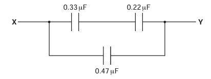
- The capacitance of each capacitor is shown.
- What is the total capacitance between X and Y?
- A. 0.25 μF
- B. 0.60 μF
- C. 1.02 μF
- D. 8.0 μF
- Answer: B
- Explain:
- The top branch has two capacitors in series:
- [math]0.33\ \mu F\ and\ 0.22\ \mu F[/math]
- [math]C_{top} = \dfrac{0.33 \times 0.22}{0.33 + 0.22}[/math]
- [math]= \dfrac{0.0726}{0.55} = 0.132\ \mu F[/math]
- The bottom branch is in parallel with the top branch and has a value of [math]0.47\ \mu\text{F}[/math].
- [math]C_{total} = C_{top} + C_{bottom}[/math]
- [math]C_{total} = 0.132 + 0.47[/math]
- [math]C_{total} = 0.602\ \mu F[/math]
- [math]C_{total} \approx 0.60\ \mu F[/math]
- 5. Y The image shows a micrometer that is being used to measure the diameter of a wire. The micrometer has a zero error of +0.07 mm. The measured value of the diameter from the micrometer scale is 2.88 mm.
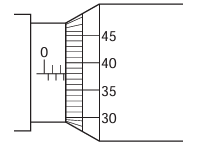
- What is the correct area of cross-section of the wire?
- A. [math]2.21 \times 10^{-6}\ m^{2}[/math]
- B. [math]6.20 \times 10^{-6}\ m^{2}[/math]
- C. [math]6.51 \times 10^{-6}\ m^{2}[/math]
- D. [math]6.84 \times 10^{-6}\ m^{2}[/math]
- Answer: B
- Explain:
- Actual Diameter Calculation:
- [math]Actual\ Diameter\ (d) = Measured\ Value – Zero\ Error[/math]
- [math]d = 2.88\ mm – 0.07\ mm = 2.81\ mm[/math]
- [math]= 2.81 \times 10^{-3}m[/math]
- Cross-Sectional Area Calculation:
- [math]A = \dfrac{\pi d^{2}}{4}[/math]
- [math]A = \dfrac{\pi \times (2.81 \times 10^{-3})^{2}}{4}[/math]
- [math]A \approx \dfrac{3.14159 \times 7.8961 \times 10^{-6}}{4}[/math]
- [math]A \approx 6.20 \times 10^{-6}m^{2}[/math]
- 6. The image shows a display of an oscilloscope which is measuring an alternating voltage. The time base is set at 0.1 s / division. The voltage scale (y-sensitivity) is set at 0.5 V / division. Which row of the table shows the correct amplitude and correct frequency?


- Answer: B
- Explain:
- Amplitude Calculation:
- Looking at the trace, the peak height from the center zero line is 3.5 divisions.
- [math]Y – sensitivity = 0.5\ V/division[/math]
- [math]Amplitude = 3.5\ divisions \times 0.5\ V/div = 1.75\ V[/math]
- Frequency Calculation:
- One complete cycle covers 4 horizontal divisions.
- Time base = 0.1 s /division
- [math]Time\ period\ (T) = 4\ divisions \times 0.1\ s/div = 0.4\ s[/math]
- [math]Frequency\ (f) = \dfrac{1}{T} = \dfrac{1}{0.4\ s}[/math]
- [math]= 2.5\ Hz[/math]
- 7. This question is about the rate of decay of a radioactive source. Which of the following statements is/are true? The rate of decay is
- dependent on the decay constant.
- independent of the mass of the source.
- dependent on time.
- A. 1 only B. 1 and 3 C. 2 only D. 2 and 3
- Answer: B
- Explain:
- The activity or rate of radioactive decay is given by the law of radioactive decay:
- [math]\dfrac{\Delta N}{\Delta t} = -\lambda N[/math]
- where [math]\lambda[/math] is the decay constant and [math]N[/math] is the number of undecayed nuclei remaining.
- Statement 1 is True: The decay rate directly depends on the decay constant [math]\lambda[/math].
- Statement 2 is False: Since N depends directly on the total mass of the radioactive source
- [math]N = \dfrac{m}{M} \times N_{A}[/math]
- A larger mass has more undecayed nuclei, which increases the rate of decay. Thus, it is dependent on the mass.
- Statement 3 is True: As time passes, nuclei decay so N decreases, making the rate of decay exponentially decrease over time.
- 8. A student is using a spreadsheet to model the decay of charge on a capacitor.
- They are using the equation
- [math]\dfrac{\Delta Q}{\Delta t} = -\dfrac{Q}{2.5}[/math]
- The student chooses a time interval of 0.5 s. At time t = 0.0 s the charge on the capacitor is 600 μC.
- Part of the modelling spreadsheet is shown below.

- Answer: D
- Explain:
- The equation given for rate of charge decay is:
- [math]\dfrac{\Delta Q}{\Delta t} = -\dfrac{Q}{2.5}[/math]
- Rearranging to find the charge decayed ([math]\Delta Q[/math]) in a time step [math]\Delta t = 0.5\ s[/math]:
- [math]\Delta Q = -\dfrac{Q}{2.5} \times \Delta t[/math]
- [math]= -Q \times \dfrac{0.5}{2.5} = -0.2 \times Q[/math]
- For each 0.5 s interval, the amount of charge lost is 20% (0.2) of the charge remaining at the start of that interval:
- [math]At\ t = 0.0\ s[/math]
- [math]Q = 600\ \mu C[/math]
- [math]\Delta Q = 0.2 \times 600 = 120\ \mu C[/math]
- [math]At\ t = 0.5\ s:[/math]
- [math]Q = 600 – 120 = 480\ \mu C[/math]
- [math]\Delta Q = 0.2 \times 480 = 96\ \mu C[/math]
- [math]At\ t = 1.0\ s:[/math]
- [math]Q = 480 – 96 = 384\ \mu C[/math]
- [math]\Delta Q = 0.2 \times 384 = 76.8\ \mu C[/math]
- [math]At\ t = 1.5\ s:[/math]
- [math]Q = 384 – 76.8 = 307.2\ \mu C[/math]
- [math]\Delta Q = 0.2 \times 307.2 = 61.44\ \mu C[/math]
- [math]At\ t = 2.0\ s:[/math]
- [math]Q = 307.2 – 61.44[/math]
- [math]= 245.76\ \mu C[/math]
- [math]\approx 246\ \mu C[/math]
- 9. The diagram shows a string stretched between two posts. The string is plucked and a stationary wave is set up.

- What is the phase difference between P and Q?
- A. 0 rad
- B. [math]\dfrac{\pi}{4}\ rad[/math]
- C. [math]\dfrac{\pi}{2}\ rad[/math]
- D. [math]\pi\ rad[/math]
- Answer: A
- Explain:
- In a stationary wave set up on a string:
- – Points in adjacent loops (antinodal sections) oscillate [math]180^{\circ}(\pi\ rad)[/math] out of phase.
- – Points in alternate loops (separated by an even number of nodes) move in phase with each other.
- Points P and Q are located in the 1st and 3rd loops respectively. Since they are separated by two nodes, they oscillate in phase with a phase difference of 0 rad.
- 10. A student uses the circuit below to determine the electromotive force (e.m.f.) and internal resistance of a battery.

- They measure the current and potential difference (p.d.) across the variable resistor for different resistor values.
- A graph is drawn with p.d. on the y-axis and current on the x-axis.
- Which row is correct for calculating the e.m.f. and the internal resistance of the battery?

- Answer: D
- Explain:
- The relationship between potential difference V, current I, e.m.f.([math]\varepsilon[/math]), and internal resistance r is given by the terminal potential difference equation:
- [math]V = \varepsilon – Ir[/math]
- Rearranging into the standard straight line form (y = mx + c):
- [math]V = (-r)I + \varepsilon[/math]
- Comparing with y = mx + c where y = V and x = I:
- y-intercept (c):
- Represents the e.m.f. ([math]\varepsilon[/math]).
- Gradient (m): Equal to -r, so the magnitude of the gradient represents the internal resistance (r).
- 11. At the Earth’s equator the magnetic flux density B is approximately 25 μT.
- What is the magnitude of the force on an electron with velocity [math]v = 100\ km\ s^{-1}[/math] as it is moving perpendicular to the Earth’s magnetic field at the equator?
- A. [math]4.0 \times 10^{-25}\ N[/math]
- B. [math]4.0 \times 10^{-22}\ N[/math]
- C. [math]4.0 \times 10^{-19}\ N[/math]
- D. [math]4.0 \times 10^{-16}\ N[/math]
- Answer: C
- Explain:
- The magnetic force on a moving charged particle is given by:
- [math]F = Bqv\sin\theta[/math]
- Given values:
- [math]B = 25\ \mu T = 25 \times 10^{-6}T[/math]
- [math]q = 1.6 \times 10^{-19}C\ (charge\ of\ an\ electron)[/math]
- [math]v = 100\ km\ s^{-1} = 100 \times 10^{3}\ m\ s^{-1} = 10^{5}\ m\ s^{-1}[/math]
- [math]\theta = 90^{\circ}\ (perpendicular\ movement,\ so\ \sin(90^{\circ}) = 1)[/math]
- [math]Substitute\ the\ values:[/math]
- [math]F = (25 \times 10^{-6}T) \times (1.6 \times 10^{-19}C) \times (10^{5}\ m\ s^{-1})[/math]
- [math]F = 40 \times 10^{-20}N = 4.0 \times 10^{-19}N[/math]
- 12. What is the radius of a carbon nucleus that has 6 protons and 7 neutrons? Assume that the average radius of a nucleon r0 is 1.2 fm.
- A. 2.2 fm
- B. 2.3 fm
- C. 2.8 fm
- D. 1.6 fm
- Answer: C
- Explain:
- The radius of a nucleus is related to its mass number A (total number of nucleons) by the formula:
- [math]R = r_{0}A^{1/3}[/math]
- [math]Given\ values:[/math]
- [math]Protons = 6,[/math]
- [math]Neutrons = 7[/math]
- [math]Mass\ number\ A = 6 + 7 = 13[/math]
- [math]r_{0} = 1.2\ fm[/math]
- [math]Substitute\ the\ values:[/math]
- [math]R = 1.2 \times (13)^{1/3}[/math]
- [math]\approx 1.2 \times 2.351 = 2.82\ fm[/math]
- [math]\approx 2.8fm[/math]
- 13. A sub-atomic particle has a positive charge.
- Which type of particle is it?
- A. anti-proton
- B. down quark
- C. neutrino
- D. positron
- Answer: D
- Explain:
- Anti-proton: Has a negative charge (-e).
- Down quark: Has a charge of [math]-\dfrac{1}{3}e[/math].
- Neutrino: Has no electric charge (0).
- Positron: Is the antiparticle of the electron and carries a positive charge (+e).
- 14. A 1.0 kΩ resistor is connected in series to a battery made of three 1.2 V cells connected as shown.
- The cells have negligible internal resistance.

- What is the reading on the ammeter?
- A. 1.2 mA
- B. 1.8 mA
- C. 2.4 mA
- D. 3.6 mA
- Answer: C
- Explain:
- Parallel Combination:
- Two of the 1.2V cells are connected in parallel. Cells of equal voltage in parallel provide an effective EMF equal to a single cell:
- [math]V_{parallel} = 1.2\ V[/math]
- Series Combination:
- This parallel combination is in series with the third 1.2V cell, and both are oriented to assist each other:
- [math]V_{total} = 1.2\ V + 1.2\ V = 2.4\ V[/math]
- Current Calculation:
- Using Ohm’s law
- [math]I = \dfrac{V}{R}[/math]
- [math]I = \dfrac{2.4\ V}{1.0 \times 10^{3}\Omega}[/math]
- [math]= 2.4 \times 10^{-3}A = 2.4\ mA[/math]
- 15. Which sequence shows the energies below in increasing order of magnitude?
- The change in kinetic energy of an electron accelerated through a potential difference of 1 V.
- The kinetic energy of a proton with a velocity of [math]1000 m^{s–1}[/math].
- The energy of an X-ray photon with a frequency of 3 × [math]10^{17} [/math]Hz.
- A. 1 2 3
- B. 3 1 2
- C. 2 1 3
- D. 1 3 2
- Answer: C
- Explain:
- Calculate the magnitude of each energy value:
- Energy 1:
- [math]E_{1} = qV[/math]
- [math]= (1.6 \times 10^{-19}C) \times (1V) = 1.6 \times 10^{-19}J[/math]
- Energy 2:
- Mass of a proton [math]m \approx 1.67 \times 10^{-27}kg[/math]
- [math]E_{2} = \dfrac{1}{2}m v^{2} = \dfrac{1}{2}(1.67 \times 10^{-27}kg) \times (1000\ m\ s^{-1})^{2}[/math]
- [math]= 8.35 \times 10^{-22}J[/math]
- Energy 3:
- Planck’s constant [math]h \approx 6.63 \times 10^{-34}J\ s[/math]
- [math]E_{3} = hf = (6.63 \times 10^{-34}J\ s) \times (3 \times 10^{17}Hz)[/math]
- [math]= 1.99 \times 10^{-16}J[/math]
- Comparing values:
- [math]E_{2}\ (8.35 \times 10^{-22}J) < E_{1}(1.6 \times 10^{-19}J) < E_{3}\ (1.99 \times 10^{-16}J)[/math]
- Thus, the sequence in increasing order of magnitude is 2, 1, 3.
-
Section B
- 16. Thermistors are circuit components whose resistance varies with temperature.
- There are two major types; negative temperature coefficient (NTC) thermistors, whose resistance decreases with increasing temperature and positive temperature coefficient (PTC) thermistors, whose resistance increases with increasing temperature.
- A student is investigating how the resistance of a thermistor varies with temperature by measuring current and voltage. The thermistor is placed in a water bath and the temperature of the water measured using a thermometer.
- The diagram below shows how the student set up the experiment (water bath not shown). The circuit has been set up incorrectly.

- a) Describe how the student should change the circuit.
- Explain:
- Circuit Corrections
- – Voltmeter placement: Move the voltmeter so that it is connected in parallel across the thermistor.
- – Ammeter placement: The ammeter must remain connected in series within the main loop of the circuit.
- Explain:
- In the provided diagram, the voltmeter is placed in series with the cell and thermistor. Voltmeters have a very high internal resistance, which prevents current from flowing properly through the main loop.
- – To measure the potential difference across the thermistor without drawing significant current, the voltmeter must be connected in parallel across it.
- – To measure the current flowing through the thermistor, the ammeter must be in series with it.
- b) The circuit was corrected and then used to collect data.
- The table shows data collected from the investigation.

- i) The axes below show a plot of current against temperature. The first four points from the table have been plotted. Plot the remaining points.
- Explain:
- Plotting Remaining Data Points
- The remaining three data points to plot from the table are:
- [math](70^{0}C,\ 2.80\ mA)[/math]
- [math](80^{0}C,\ 3.66\ mA)[/math]
- [math](90^{0}C, 4.76\ mA)[/math]
- Explain:
- Locate [math]70^{0}C[/math] on the horizontal axis and mark the point vertically up at 2.80 mA (4 small squares above 2.6 mA or 8 small grid squares above 2.0 mA, as each small vertical square represents 0.1 mA).
- At [math]80^{0}C[/math], place the mark slightly above 3.6 mA (3.66 mA is roughly three-fifths into the square between 3.6 mA and 3.7 mA).
- At [math]90^{0}C[/math], place the mark at 4.76 mA (roughly three-quarters into the square between 4.7 mA and 4.8 mA).
- ii) Draw a suitable line of best fit through the data points.

- Explain:

- Draw a smooth, continuous curve that passes through (or close to) all seven plotted points. The curve should bend upwards, getting progressively steeper as the temperature increases, showing a non-linear relationship.
- c) Describe, using the graph and calculations using data from the table, how the resistance of the thermistor varies for increasing temperature.
- Hence determine whether the thermistor the student used was an NTC or a PTC thermistor.
- Explain:
- Variation of Resistance & Thermistor Type
- Resistance Trend:
- As the temperature increases, the resistance of the thermistor decreases.
- Thermistor Type: It is an NTC (Negative Temperature Coefficient) thermistor.
- Explain:
- Using Ohm’s law
- [math]R = \dfrac{V}{I}[/math]
- [math]At\ 30^{\circ}C[/math]
- [math]R = \dfrac{3.00\ V}{0.75 \times 10^{-3}A} = 4000\ \Omega[/math]
- [math]= 4.0\ k\Omega[/math]
- [math]At\ 60^{\circ}C:[/math]
- [math]R = \dfrac{3.00\ V}{2.10 \times 10^{-3}A}\approx 1429\ \Omega[/math]
- [math]\approx 1.43\ k\Omega[/math]
- [math]At\ 90^{\circ}C[/math]
- [math]R = \dfrac{3.00\ V}{4.76 \times 10^{-3}A}\approx 630\ \Omega[/math]
- [math]= 0.63\ k\Omega[/math]
- Since the voltage remains constant (3.00 V) while the current I increases with temperature (as seen on the upward-curving graph), the resistance R must decrease as temperature rises. By definition, a thermistor whose resistance decreases as temperature increases is an NTC thermistor.
- d) The thermistor is used in a temperature-sensing circuit for a heating system to warm milk for a baby.
- The student considers two possible designs for the circuit which are shown below.

- In each circuit, the voltage Vout across the thermistor is connected to the heating system for warming the milk. Discuss which circuit may be suitable for the heating system by considering the response of the circuit to changes in temperature.
- Explain:
- Circuit 1:
- The thermistor is connected directly across the 3.00 V power supply. Therefore, [math]V_{out}[/math] across the thermistor will always equal 3.00 V, regardless of temperature changes. Because [math]V_{out}[/math] remains constant, Circuit 1 cannot sense or respond to changes in temperature.
- Circuit 2:
- This circuit forms a potential divider using the fixed [math]10\ k\Omega[/math] resistor and the NTC thermistor.
- As temperature increases, the thermistor’s resistance decreases.
- By the potential divider formula
- [math]V_{out} = V_{in} \times \dfrac{R_{thermistor}}{R_{fixed} + R_{thermistor}}[/math]
- a lower thermistor resistance takes a smaller share of the 3.00 V supply.
- Thus, [math]V_{out}[/math] decreases as temperature rises (or increases as temperature falls).
- This changing output voltage allows the heating system to detect temperature changes (e.g., turning off the heater when the milk becomes warm enough).
- 17. The diagram shows two identical loudspeakers X and Y connected to a signal generator. The loudspeakers emit sound waves of the same amplitude and frequency which are in phase.
- A microphone M is moved along a line from P1 to P3 and the signal recorded on an oscilloscope.

- As the microphone is moved along the line P1 to P3 the oscilloscope shows maximum signal at P1, zero signal at P2 and the next maximum signal at P3.
- a) Explain these observations.
- Explain:
- Explanation:
- This phenomenon is caused by two-source interference of coherent sound waves:
- At [math]P_{1}[/math]: The path difference between the sound waves from X and Y is zero (or an integral number of wavelengths, [math]n\lambda[/math]). The waves arrive in phase, producing constructive interference, which results in a maximum signal (maximum amplitude).
- At [math]P_{2}[/math]: The path difference is equal to half a wavelength [math]\dfrac{1}{2} \lambda[/math]. The waves arrive in antiphase [math](180^{\circ}\ out\ of\ phase)[/math], producing destructive interference, which results in zero signal (minimum amplitude).
- At [math]P_{3}[/math]: The path difference increases to one full wavelength [math]\lambda[/math]. The waves arrive in phase again, leading to constructive interference and the next maximum signal.
- b) The distance between the centres of X and Y is 70.0 cm, the distance D (as shown in the diagram) is 4.00 m and the distance from P1 to P2 is 1.25 m.
- Use the two source interference formula to calculate the frequency of the sound waves. ([math]Speed\ of\ sound = 340\ m\ s^{-1}[/math])
- Explain:
- Identify the Given Values:
- Slit/speaker separation, a = 70.0 cm = 0.700 m
- Distance to line of observation, D = 4.00 m
- Distance between maximum ([math]P_{1}[/math]) and minimum ([math]P_{2}[/math]) = 1.25 m
- Since [math]P_{1}[/math] to [math]P_{3}[/math] represents one full fringe spacing (x), the fringe spacing x (distance between two consecutive maxima [math]P_{1}[/math] to [math]P_{3}[/math]) is:
- [math]x = 2 \times 1.25\ m = 2.50\ m[/math]
- Calculate Wavelength ([math]\lambda[/math]):
- Using the double-source interference formula
- [math]\lambda = \dfrac{a.x}{D}[/math]
- [math]\lambda = \dfrac{0.700\ m \times 2.50\ m}{4.00\ m}= 0.4375\ m[/math]
- Calculate Frequency (f):
- Assuming the standard speed of sound in air, v = 330 m/s (or 340 m/s depending on the standard specification; using v = 330 m/s:
- [math]f = \dfrac{330}{0.4375}[/math]
- [math]\approx 754\ Hz[/math]
- [math]If\ v = 340\ m/s\ is\ used:[/math]
- [math]f = \dfrac{340}{0.4375}[/math]
- [math]\approx 777\ Hz)[/math]
- c) Loudspeaker Y is now replaced with a loudspeaker that produces sound waves of twice the original amplitude.
- Describe how the signal observed on the oscilloscope varies as the microphone is moved along the line P1 to P3.
- Explain:
- At Maxima ([math]P_{1}[/math] and [math]P_{3}[/math]):
- The original amplitude from each speaker was A, giving a combined maximum amplitude of A + A = 2A.
- Now speaker Y has amplitude 2A. At [math]P_{1}[/math] and [math]P_{3}[/math], the waves interfere constructively:
- [math]Total\ Amplitude = A + 2A = 3A[/math]
- The signal amplitude on the oscilloscope increases (it is larger than before).
- At Minima ([math]P_{2}[/math]):
- The waves interfere destructively:
- [math]Total\ Amplitude = |2A – A| = a[/math]
- The signal is no longer zero; a non-zero minimum signal will now be observed.
- d) .
- i) Explain what is meant by the term intensity.
- Explain:
- Intensity is defined as the radiant power per unit area incident normally on a surface.
- [math]Intensity\ (I) = \dfrac{Power}{Area}[/math]
- iii) Calculate the factor by which the intensity of the sound waves at P1 in (c) is larger than the intensity of the original sound waves at P1.
- Explain:
- Factor Calculation
- Original Intensity at P1:
- Original resultant amplitude,
- [math]A_{1} = A + A = 2A[/math]
- Original intensity,
- [math]I_{1} \propto (2A)^{2} = 4A^{2}[/math]
- New Intensity at [math]P_{1}[/math]:
- New resultant amplitude,
- [math]A_{2} = A + 2A = 3A[/math]
- New intensity,
- [math]I_{2} \propto (3A)^{2} = 9A^{2}[/math]
- Ratio Factor:
- [math]Factor = \dfrac{I_{2}}{I_{1}} = \dfrac{9A^{2}}{4A^{2}}[/math]
- [math]= \dfrac{9}{4} = 2.25[/math]
- 18.
- a) Describe how an experiment can be conducted to determine how the output current of a step-up transformer depends on the number of turns on the secondary coil.
- Explain how the data collected can be analysed to establish the relationship between the output current and the number of turns on the secondary coil.
- You are provided with wire and a suitable core on which to wind the wire, as well as any other normal laboratory equipment.
- Use the space below to draw a labelled circuit diagram.
- Explain:
- Setup:
- Wind a fixed number of turns (e.g., [math]N_{p} = 100[/math]) of insulated copper wire onto one side of the soft iron core to form the primary coil.
- Connect an AC power supply in series with an AC ammeter ([math]A_{1}[/math]) and the primary coil.
- Wind a known number of turns (e.g., [math]N_{s} = 200,\ ensuring\ N_{s} > N_{p}[/math] for a step-up transformer) onto the opposite side of the iron core to form the secondary coil.
- Connect the secondary coil in series with an AC ammeter ([math]A_{2}[/math]) and a fixed-value resistor (R) to form a complete closed circuit.
- Method:
- Set the AC power supply to a constant alternating voltage and constant frequency.
- Switch on the supply and record the primary current [math]I_{p}\ (on\ A_{1})[/math] and the secondary output current [math]I_{s}(on\ A_{2})[/math].
- Switch off the supply, change the secondary coil by increasing the number of turns [math]N_{s}\ (e.g.,\ N_{s} = 250, 300, 350, 400, 450)[/math], ensuring the load resistance R and primary supply voltage remain constant.
- Repeat the measurements of [math]I_{s}[/math] for each value of [math]N_{s}[/math].
- Control Variables:
- Input primary voltage ([math]V_{p}[/math]) and frequency.
- Fixed primary turns ([math]N_{p}[/math]).
- Secondary load resistance (R).
- Data Analysis:
- Tabulate the values of [math]N_{s}\ and\ I_{s}[/math].
- Plot a graph of secondary current.
- [math](I_{s}) vs. \dfrac{1}{N_{s}}\ (or\ I_{s}\ vs.\ N_{s})[/math]
- Theoretical Expectation:
- For an ideal transformer,
- [math]V_{s}I_{s} = V_{p}I_{p}[/math] and [math]\dfrac{V_{s}}{V_{p}} = \dfrac{N_{s}}{N_{p}}[/math]
- Therefore,
- [math]V_{s} = \left(\dfrac{N_{s}}{N_{p}}\right)V_{p}[/math]
- Since
- [math]I_{s} = \dfrac{V_{s}}{R}[/math]
- we have:
- [math]V_{s} = \left(\dfrac{V_{p}}{R.N_{p}}\right)N_{s}[/math]
- If [math]I_{s}[/math] is directly proportional to [math]N_{s}[/math], a graph of [math]I_{s}[/math] against [math]N_{s}[/math] will be a straight line passing through the origin.
- If a constant power supply/load condition is used where secondary voltage is fixed, [math]I_{s}[/math] would be inversely proportional to [math]N_{s}[/math], yielding a straight line passing through the origin when [math]I_{s}[/math] is plotted against
- [math]\dfrac{1}{N_{s}}[/math]
- b) A simple laminated iron-core transformer takes mains voltage 230 V, 50 Hz into the primary coil. The output voltage from the secondary coil is 5.0 V. The primary coil has 920 turns.
- i) State Faraday’s law
- Explain:
- Faraday’s Law of Electromagnetic Induction states that:
- The magnitude of the induced electromotive force (e.m.f.) in a circuit is directly proportional to the rate of change of magnetic flux linkage through the circuit.
- [math]\varepsilon = -N\dfrac{\Delta\Phi}{\Delta t}[/math]
- ii) Show that the number of turns on the secondary coil is 20.
- Explain:
- Using the transformer turns ratio formula:
- [math]\dfrac{V_{s}}{V_{p}} = \dfrac{N_{s}}{N_{p}}[/math]
- Given:
- [math]V_{p} = 230\ V[/math]
- [math]V_{s} = 5.0\ V[/math]
- [math]N_{p} = 920[/math]
- Rearranging for [math]N_{s}[/math]:
- [math]N_{s} = N_{p} \times \dfrac{V_{s}}{V_{p}}[/math]
- [math]N_{s} = 920 \times \dfrac{5.0}{230}[/math]
- [math]N_{s} = 920 \times \dfrac{1}{46}[/math]
- [math]N_{s} = 20[/math]
- iii) At one particular instant, the output voltage from the transformer is 3.4 V.
- Calculate the change in magnetic flux experienced by the secondary coil in a short time interval of 1.2 ms and state its unit.
- Assume that the output voltage from the transformer remains constant at 3.4 V over this time interval.
- Explain:
- Formula:
- From Faraday’s law, the magnitude of induced e.m.f. ([math]V_{s}[/math]) across the secondary coil is given by:
- [math]V_{s} = N_{s}\dfrac{\Delta\Phi}{\Delta t}[/math]
- Rearranging for the change in magnetic flux ([math]\Delta\Phi[/math])
- [math]\Delta\Phi = \dfrac{V_{s} \times \Delta t}{N_{s}}[/math]
- Given Data:
- [math]V_{s} = 3.4\ V[/math]
- [math]\Delta t = 1.2\ ms = 1.2 \times 10^{-3}s[/math]
- [math]N_{s} = 20[/math]
- [math]\Delta\Phi = \dfrac{V_{s} \times \Delta t}{N_{s}}[/math]
- [math]\Delta\Phi = \dfrac{3.4 \times 1.2 \times 10^{-3}}{20}[/math]
- [math]\Delta\Phi = 2.04 \times 10^{-4}\ Wb[/math]