
22 May 2024
-
SECTION A
-
Answer ALL questions.
- All multiple-choice questions must be answered with a cross in the box for the correct answer from A to D. If you change your mind about an answer, put a line through the box and then mark your new answer with a cross.
- 1. The graph shows how the displacement of particles in a progressive wave varies with distance along the wave, at a particular instant.
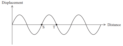
- Which of the following is the phase difference between the particles at S and T?
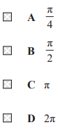
- Answer: C
- Explain:
- The phase difference between two points on a wave depends on the distance between them relative to the wavelength ([math]\lambda[/math])
- – One full wavelength ([math]\lambda[/math]) corresponds to a phase difference of [math]2\pi[/math] radians.
- – The distance between points S and T in the provided graph is exactly half a wavelength ([math]\lambda/2[/math]). Point S is at a zero-crossing moving upwards (implied by the shape), while point T is at a zero-crossing moving downwards.
- – The phase difference ([math]\Delta\phi[/math]) can be calculated using the formula:
- [math]\Delta\phi=2\pi d/\lambda[/math]
- [math]d=\lambda/2[/math]
- [math]\Delta\phi=2\pi(\lambda/2)/\lambda[/math]
- [math]\Delta\phi=\pi[/math]
- 2. Two diverging lenses are combined, as shown.
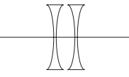
- The focal length of each lens is [math]0.2,\text{m}[/math].
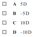
- Which of the following is the total power of the combination?
- Answer: D
- Explain:
- – The focal length of each lens = [math]-0.2,\text{m}[/math]
- Calculate the power of a single lens:
- [math]P=1/f[/math]
- [math]P=1/(-0.2)[/math]
- [math]P=-5,\text{D}[/math]
- Calculate the total power of the combination:
- [math]P_{\text{total}}=P_1+P_2[/math]
- [math]P_{\text{total}}=-5,\text{D}+(-5,\text{D})[/math]
- [math]P_{\text{total}}=-10,\text{D}[/math]
- 3. An electron in an atom absorbs energy [math]E[/math] and is excited from one energy level to the next.
- When the electron returns to its original energy level a photon is emitted.
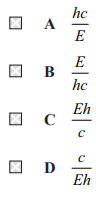
- Which of the following is an expression for the wavelength of the emitted photon?
- Answer: A
- Explain:
- Understand the energy of the emitted photon
– The problem states that the electron absorbs energy [math]E[/math] to get excited. When it returns to its original level, it emits a photon with the exact same energy [math]E[/math]. - Use the Planck-Einstein relation:
- [math]E=hc/\lambda[/math]
- [math]\lambda=hc/E[/math]
- 4. The image formed by a lens can be described as real or virtual.
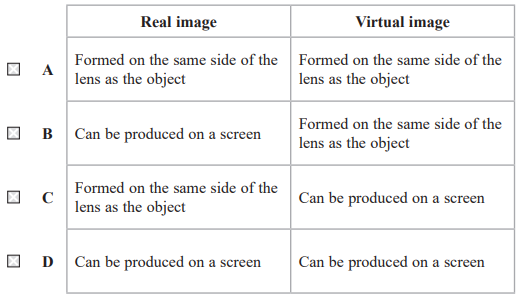
- Which row of the table describes a real image and a virtual image?
- Answer: B
- Explain:
- Can be produced on a screen | Formed on the same side of the lens as the object
- A real image is formed when light rays actually converge and intersect at a point after passing through a lens. Because the light rays converge, a real image can be projected onto a screen.
- A virtual image is formed when light rays appear to diverge from a point but do not actually intersect. Virtual images cannot be produced on a screen. For a single lens, a virtual image is formed on the same side of the lens as the object.
- 5. The photoelectric effect provides evidence for the particle nature of electromagnetic radiation.
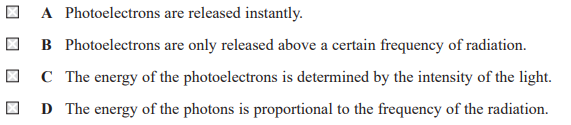
- Which of the following is not observed in the photoelectric effect?
- Answer: C
- Explain:
- The energy of the photoelectrons is determined by the intensity of the light.
- (A) Photoelectrons are released instantly:
- – This is observed in the photoelectric effect. The emission of photoelectrons occurs almost immediately (instantaneously) upon absorption of a photon, provided the frequency is above the threshold.
- (B) Photoelectrons are only released above a certain frequency of radiation:
- – This is a key observation. A minimum frequency (threshold frequency) is required for electron emission, regardless of the light’s intensity.
- (C) The energy of the photoelectrons is determined by the intensity of the light:
- – This is not observed. The maximum kinetic energy of the emitted photoelectrons is independent of the light’s intensity and is proportional to the frequency of the light. The intensity of the light determines the number of photoelectrons emitted (the photoelectric current), not their energy.
- (D) The energy of the photons is proportional to the frequency of the radiation:
- – This is a fundamental principle of quantum mechanics which explains the observations of the photoelectric effect.
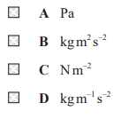
- 6. Which of the following is the S.I. base unit for breaking stress?
- Answer: B
- Explain:
- Stress=Force/Area
- [math]\text{Stress}=F/A[/math]
- [math]\text{Stress}=(\text{kg·m·s}^{-2})/m^2[/math]
- [math]\text{Pa}=\text{kg·m}^{-1}\text{s}^{-2}[/math]
- 7. A ball bearing with radius r falls through a fluid with density ρ.
Which of the following is an expression for the upthrust acting on the ball bearing? 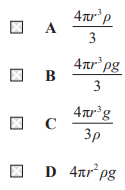
- Answer: B
- Explain:
- Upthrust on a ball bearing:
- [math]F_B=V\rho g[/math]
- [math]V=\frac{4}{3}\pi r^3[/math]
- [math]F_B=\frac{4}{3}\pi r^3\rho g[/math]
- 8. Unpolarised light passes through two polarising filters, as shown. The planes of polarisation of the two filters are parallel.
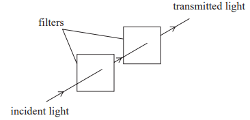
- One filter is rotated so that the planes of polarisation of the two filters are perpendicular.
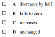
- Which of the following describes the change to the intensity of the transmitted light?
- Answer: B
- Explain:
- This polarised light then passes through the second filter with minimal loss (ignoring some absorption by the material itself).
- – When the second filter is rotated so that its plane of polarisation is perpendicular to the first filter’s plane, the orientation of the second filter blocks all the light that was transmitted by the first filter.
- – According to Malus’s Law, the transmitted intensity [math]I[/math] is given by
- [math]I=I_0\cos^2\theta[/math]
- Where [math]I_0[/math] is the incident intensity on the second filter and [math]\theta[/math] is the angle between the two filter axes.
- When the filters are perpendicular,
- [math]\theta=90^0[/math]
- [math]\cos(90^0)=0[/math]
- [math]I=I_0(0)[/math]
- [math]I=0[/math]
- Therefore, the intensity of the transmitted light falls to zero.
- 9. A telescope is used to produce a magnified image of a full Moon. The telescope consists of two converging lenses, the objective lens and the eyepiece lens, as shown.
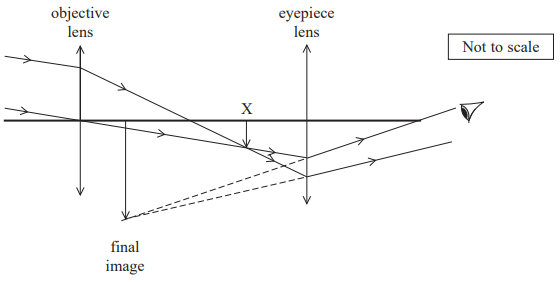
- The objective lens produces an inverted image at point X. The image at point X is the object for the eyepiece lens. The eyepiece lens produces a magnified image.
- (a) The power of the objective lens is 0.8D. Calculate the distance of the image at X from the objective lens. (3)
- Explain:
- – The problem states that the telescope is used to view a “full Moon”. For astronomical objects like the Moon, the object distance is considered to be infinity. The objective lens produces an image at point X. When the object is at infinity, the image is formed at the principal focus of the converging lens. Therefore, the image distance (distance to point X) is equal to the focal length of the objective lens.
- – The power of the objective lens = [math]P=0.8\text{ D}[/math]
- Calculate the focal length:
- [math]f=1/P[/math]
- [math]f=1/(0.8)[/math]
- [math]f=1.25\text{ m}[/math]
- Determine the image distance
- – Since the image at point X is formed at the principal focus, the distance of the image at X from the objective lens is equal to the focal length.
- Distance = [math]f=1.25\text{ m}[/math]
- Distance = [math]f=1.25\text{ m}[/math]
- (b) Complete the ray diagram, to scale, to determine the magnification of the image formed by the eyepiece lens. (4)
- Explain:
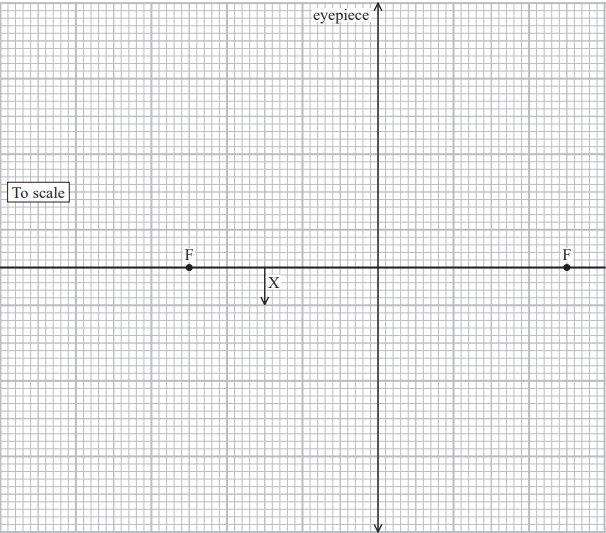
- Explain:
- Draw the image formed by the objective lens
- – The objective lens produces an inverted image at point X. The diagram shows two rays from the top of the object (the full Moon) converging to point X. The image formed at X is the object for the eyepiece lens.
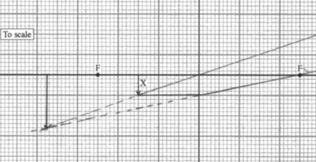
- Draw rays from the top of the object at X through the eyepiece lens
- – Draw two rays from the top of the object at point X through the eyepiece lens, following the rules for ray diagrams:
- – One ray should be drawn horizontally from the top of the object at X to the eyepiece lens. This ray should refract away from the principal axis, as if it originated from the principal focus of the eyepiece lens on the left side.
- – A second ray should be drawn from the top of the object at X through the optical center of the eyepiece lens, continuing undeviated.
- Extend the refracted rays backwards to form the final image
- – Extend the two refracted rays backwards until they appear to intersect. The intersection point is the top of the final, magnified, virtual image. Draw an upright arrow from the principal axis to this intersection point to represent the final image.
- Determine the magnification
- – The magnification can be determined by measuring the height of the final image and the height of the object at X using the scale of the grid provided. The magnification is the ratio of the image height to the object height:
- [math]\text{Magnification}=(\text{Image distance})/(\text{Object distance})[/math]
- – Image distance = [math]v=7.5\text{ cm}[/math]
- – Object distance = [math]u=3\text{ cm}[/math]
- [math]\text{Magnification}=7.5/3.0[/math]
- [math]\text{Magnification}=2.5[/math]
- Magnification = 2.5
- 10. Scientists can use a pulse echo technique with ultrasound to detect plastic in the oceans. A transducer that emits and detects ultrasound pulses is positioned just below the surface of the water.
- (a) An ultrasound pulse was transmitted. The pulse was reflected from a piece of plastic under the surface and the pulse was detected 4.1ms later. Calculate the distance between the plastic and the transducer.
- – Speed of sound in salt water = 1500 m.s–1 (3)
- Explain:
- – Time = [math]t_{total}=4.1\text{ ms}[/math]
- [math]t_{total}=4.1\times10^{-3}\text{ s}[/math]
- Use the speed formula to find the total distance traveled:
- – The speed of sound in salt water = [math]v=1500\text{ m·s}^{-1}[/math]
- [math]d_{total}=v\times t_{total}[/math]
- [math]d_{total}=1500\times4.1\times10^{-3}[/math]
- [math]d_{total}=6.15\text{ m}[/math]
- Calculate the distance between the plastic and the transducer
- – The total distance is twice the distance between the transducer and the plastic because the pulse travels to the plastic and then reflects back.
- [math]d_{total}=2\times d_{plastic}[/math]
- [math]d_{plastic}=d_{total}/2[/math]
- [math]d_{plastic}=6.15/2[/math]
- [math]d_{plastic}=3.075\text{ m}[/math]
- Distance = 3.075 m
- (b) Give a reason why the ultrasound is emitted in short pulses. (1)
- Explain:
- – To allow enough time for the echo to return to the transducer before the next pulse is emitted
- – The use of short pulses with sufficient time gaps between them is crucial for the pulse-echo technique. This time gap allows the transducer to switch from “sending” to “listening” mode and detect the returning echoes from the target (in this case, plastic in the ocean). Without these gaps, the echo from a target might arrive while the transducer is still emitting a pulse, making it impossible to distinguish the echo from the outgoing signal.
- (c) Explain why small pieces of plastic are more likely to be detected by using ultrasound with a high frequency. (2)
- Explain:
- – Small pieces of plastic are more likely to be detected by using ultrasound with a high frequency because the wavelength of the ultrasound wave is inversely proportional to its frequency, and a high frequency results in a shorter wavelength. For effective detection via reflection (pulse-echo technique), the wavelength of the wave must be comparable to or smaller than the size of the object being detected.
- The ability of a wave to reflect off an object efficiently depends on the relative size of the object compared to the wavelength of the wave. The relationship between frequency ([math]f[/math]), wavelength ([math]\lambda[/math]) and wave speed ([math]v[/math]) is given by the equation
- [math]v=f\lambda[/math]
- – For high-frequency ultrasound, the wavelength ([math]\lambda[/math]) is short.
- – Small plastic pieces have small dimensions.
- When the wavelength of the ultrasound is comparable to or smaller than the size of the plastic pieces, the waves are scattered and reflected effectively, allowing the transducer to detect the echoes.
- – If a low-frequency (long wavelength) ultrasound were used, the waves would pass around the small plastic pieces with little to no reflection, making them undetectable.
- 11. A technician shone light from a laser through a diffraction grating. A pattern was observed on a screen [math]4.00\text{m}[/math] away. The pattern consisted of [math]5[/math] maxima, as shown.
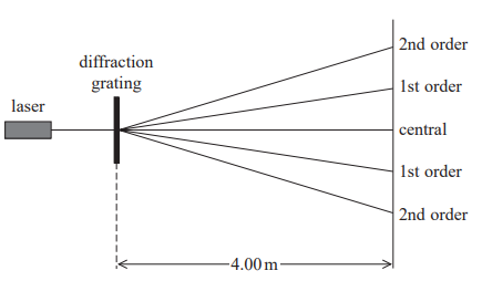
- The diffraction grating has [math]4.00 \times 10^2[/math] lines per millimetre.
- (a) The technician wanted to check that the wavelength emitted by the laser was within the range [math]450\text{nm} \pm 10\text{nm}[/math].
- She measured the distance between the two second order maxima as [math]3.25\text{m}[/math].
- Deduce whether the light from the laser was within the range [math]450\text{nm} \pm 10\text{nm}[/math]. (4)
- Explain:
- Calculate the grating spacing, [math]d[/math]
- – The grating [math]d = 4.00 \times 10^2[/math] lines per millimeter
- [math]d = \frac{1}{4.00 \times 10^2 \text{ lines / mm}}[/math]
- [math]d = \frac{1}{4.00 \times 10^5 \text{ lines / m}}[/math]
- [math]d = 2.50 \times 10^{-6}\text{m}[/math]
- – The distance from the grating to the screen = [math]L = 4.00\text{m}[/math]
- [math]\tan \theta = \frac{y}{L}[/math]
- [math]\tan \theta = \frac{1.625}{4.00}[/math]
- [math]\tan \theta = 0.40625[/math]
- [math]\theta = \tan^{-1}(0.40625)[/math]
- [math]\theta = 22.1[/math]degree
- Calculate the wavelength
- – [math]n = 2[/math] for the second order
- [math]\lambda = \frac{d \sin \theta}{n}[/math]
- [math]\lambda = \frac{(2.50 \times 10^{-6}) \sin 22.1^\circ}{2}[/math]
- [math]\lambda = 4.70 \times 10^{-7}\text{m}[/math]
- [math]\lambda = 470 \times 10^{-9}\text{m}[/math]
- [math]\lambda = 470\text{nm}[/math]
- The required range for the wavelength is [math]470\text{nm} \pm 10\text{nm}[/math], which is from [math]440\text{nm}[/math] to [math]460\text{nm}[/math].
- (b) The electrons in an electron beam have a speed of approximately [math]10%[/math] of the speed of light. It is possible to demonstrate diffraction with this electron beam when the electron beam is incident on a graphite target.
- If the spacing of the atoms in the graphite target were equal to the spacing of lines on the diffraction grating used by the technician, this electron beam would not show diffraction effects.
- Explain why. Your answer should include calculations. (4)
- Explain:
- – The number or line per millimeter = [math]4 \times 10^5[/math]
- – The distance [math]d[/math] between the lines is the reciprocal of the number of lines per meter.
- [math]d = \frac{1}{4 \times 10^5}[/math]
- [math]d = 2.50 \times 10^{-6}\text{m}[/math]
- Calculate the de Broglie wavelength of the electrons
- – [math]10%[/math] of the speed of light = [math]0.10 \times 3 \times 10^8\text{m/s} = 3 \times 10^7\text{m/s}[/math]
- – Planck’s constant = [math]h = 6.63 \times 10^{-34}\text{Js}[/math]
- – [math]m = 9.11 \times 10^{-31}\text{kg}[/math]
- [math]\lambda = \frac{h}{mv}[/math]
- [math]\lambda = \frac{6.63 \times 10^{-34}}{(9.11 \times 10^{-31})(3 \times 10^7)}[/math]
- [math]\lambda = 2.42 \times 10^{-11}\text{m}[/math]
- Compare the wavelength to the spacing and explain why diffraction does not occur:
- – For noticeable diffraction to occur, the wavelength of the incident wave must be comparable to the size of the gap or spacing.
- – The de Broglie wavelength of the electrons ([math]2.42 \times 10^{-11}\text{m}[/math]) is significantly smaller than the spacing of the diffraction grating lines ([math]2.50 \times 10^{-6}\text{m}[/math]). The spacing is approximately [math]100{,}000[/math] times larger than the wavelength. Because the wavelength is much smaller than the gap size, diffraction effects would be unnoticeable.
- 12. A student investigated the properties of metal wires.
- (a) Describe how the student should determine the diameter of a wire. (3)
- Explain:
- A micrometer screw gauge or Vernier calipers should be used to measure the diameter of the wire.
- The student should first determine the instrument’s least count and check for any zero error.
- The wire should be placed between the anvil and the spindle of the micrometer, and the ratchet turned until the wire is gently held.
- Multiple measurements of the diameter should be taken at different points along the wire and in different orientations to account for any variations in thickness or a non-circular cross-section.
- The average of these measurements should be calculated to obtain a more precise value for the wire’s diameter.