
17 May 2019
-
SECTION A
-
Answer ALL questions.
- All multiple choice questions must be answered with a cross in the box for the correct answer from A to D. If you change your mind about an answer, put a line through the box. and then mark your new answer with a cross.
- 1. A sample of steel in the form of a wire is subjected to an increasing load.
- Which of the following is the best description of the elastic limit of the steel?
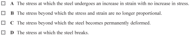
- Answer: C
- Explain:
- The elastic limit is the maximum stress that a material can withstand without undergoing permanent deformation. When a material is stressed beyond its elastic limit, it will not return to its original shape once the stress is removed. This permanent deformation is called plastic deformation.
- 2. Radar is used to detect the position of an aircraft. Microwave pulses are emitted from the radar transducer. The pulses reflect from the aircraft and are received back at the same transducer. The time in seconds between emission and reception of the pulse is 1.
- The distance of the aircraft in metres from the transducer is given by
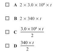
- Answer: C
- Explain:
- [math]2d=c\times t[/math]
- [math]2d=3.0\times10^{8}\times t[/math]
- [math]d=\dfrac{3.0\times10^{8}\times t}{2}[/math]
- 3. Some of the energy levels of an atom of a gas are shown.
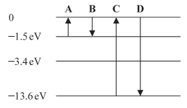
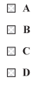
- During which transition, A, B, C or D, is electromagnetic radiation with the shortest wavelength emitted?
- Answer: D
- Explain:
- Electromagnetic radiation is emitted when an electron transitions from a higher energy level to a lower energy level. The energy of the emitted photon is equal to the difference in energy between the two levels. The relationship between the energy of a photon (E), its wavelength ([math]\lambda[/math]), and the speed of light (c) and Planck’s constant (h) is given by the equation:
- [math]E=\dfrac{hc}{\lambda}[/math]
- From this equation, we can see that energy and wavelength are inversely proportional. This means that the transition with the greatest energy change will emit radiation with the shortest wavelength.
- Let’s calculate the energy change for each transition:
- Transition A:
- The electron absorbs energy to move from [math]-13.6\ \text{eV}[/math] to [math]-3.4\ \text{eV}[/math]. This is an absorption, not an emission. The energy difference is
- [math]-3.4-(-13.6)=10.2\ \text{eV}[/math]
- Transition B:
- The electron transitions from [math]-1.5\ \text{eV}[/math] to [math]-13.6\ \text{eV}[/math]. The energy emitted is
- [math]-13.6-(-1.5)=-12.1\ \text{eV}[/math]
- The magnitude of the energy is [math]12.1\ \text{eV}[/math].
- Transition C:
- The electron transitions from [math]0\ \text{eV}[/math] to [math]-3.4\ \text{eV}[/math]. The energy emitted is
- [math]-3.4-0=-3.4\ \text{eV}[/math]
- The magnitude of the energy is [math]3.4\ \text{eV}[/math].
- Transition D:
- The electron transitions from [math]0\ \text{eV}[/math] to [math]-13.6\ \text{eV}[/math]. The energy emitted is
- [math]-13.6-0=-13.6\ \text{eV}[/math]
- The magnitude of the energy is [math]13.6\ \text{eV}[/math].
- Comparing the magnitudes of the emitted energy, transition D has the largest energy change ([math]13.6\ \text{eV}[/math]), which corresponds to the shortest wavelength of emitted electromagnetic radiation.
- 4. The Hooke’s law equation is:
- [math]\Delta F=k\Delta x[/math]
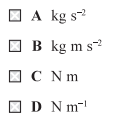
- Which of the following gives the base units of k?
- Answer: A
- Explain:
- By using the Hooke’s law
- [math]\Delta F=k\Delta x[/math]
- [math]k=\dfrac{\Delta F}{\Delta x}[/math]
- By using units
- [math]k=\dfrac{\Delta(\text{kg}\cdot\text{m}\cdot\text{s}^{-2})}{\Delta(\text{m})}[/math]
- [math]k=\text{kg}\cdot\text{s}^{-2}[/math]
- 5. A ray of light travels through medium 1 of refractive index n_1 and is incident at an interface with medium 2 of refractive index n_2 The ray is totally internally reflected at the interface.
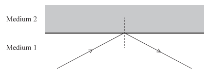
- speed of the light in medium 1 = [math]v_1[/math]
- speed of the light in medium 2 =[math] v_2[/math]
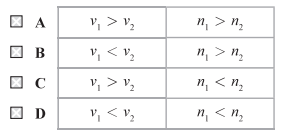
- Which row of the table is correct for this situation?
- Answer: B
- Explain:
- Based on the principles of total internal reflection, the correct answer is option B.
- Here is the reasoning:
- For total internal reflection to occur, light must travel from a denser medium to a less dense medium. This means the refractive index of the first medium ([math]n_1 [/math]) must be greater than the refractive index of the second medium ([math]n_2 [/math]) Therefore, [math]n_1>n_2[/math].
- The relationship between the refractive index (n) of a medium, the speed of light in a vacuum (c), and the speed of light in that medium (v) is given by the formula
- [math]n=\dfrac{c}{v}[/math]
- From this relationship, it can be deduced that the speed of light is inversely proportional to the refractive index of the medium. Since the light is moving from a medium with a higher refractive index ([math]n_1 [/math]) to a medium with a lower refractive index ([math]n_2 [/math]) the speed of light must be greater in the second medium. Thus, the speed of light in medium 1 ([math]v_1 [/math]) is less than the speed of light in medium 2 ([math]v_2[/math] ). Therefore [math]v_1<v_2[/math].
- Questions 6 and 7 refer to the following information.
- In an experiment to determine the speed of sound in air, a 2-beam oscilloscope is used to display the signals from two microphones. The microphones are placed in front of a loudspeaker that is connected to a signal generator.
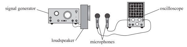
- The loudspeaker emits a sound of frequency f.
- 6. The microphones are placed at different distances from the loudspeaker. The time taken for the sound to travel from the first microphone to the second is t.
- Which of the following expressions gives the phase difference between the two signals?
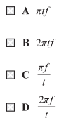
- Answer: B
- Explain:
- The phase difference ([math]\Delta\phi[/math]) between two waves is directly proportional to the time difference ([math]\Delta t[/math]) between them. The relationship is given by the formula:
- [math]\Delta\phi=\dfrac{\Delta t}{T}\times2\pi[/math]
- Where T is the period of the wave.
- The period (T) of a wave is the reciprocal of its frequency (f):
- [math]T=\dfrac{1}{f}[/math]
- In this problem, the time taken for the sound to travel from the first microphone to the second is given as t, so [math]\Delta t=t [/math]into the phase difference formula, the expression becomes:
- [math]\Delta\phi=\dfrac{t}{1/f}\times2\pi[/math]
- [math]\Delta\phi=tf\times2\pi[/math]
- [math]\Delta\phi=tf2\pi[/math]
- 7. The microphones are placed at equal distances from the loudspeaker. The signals are in phase. One of the microphones is moved further away from the loudspeaker. Initially the signals become out of phase. After moving the microphone a distance d the signals are back in phase.
- Which of the following expressions gives the speed of sound?
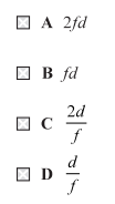
- Answer: B
- Explain:
- Problem Analysis
- The problem describes an experiment to determine the speed of sound using a loudspeaker, two microphones, and a 2-beam oscilloscope.
- – Initially, the microphones are placed at equal distances from the loudspeaker, and the signals are in phase. This means the sound waves arrive at both microphones at the same point in their cycle.
- – One microphone is then moved a distance, d, away from the loudspeaker.The signals are “back in phase” after moving this distance d.
- Conceptual Explanation
- – The speed of a wave v, is related to its frequency, f and wavelength by the equation:
- [math]v=f\lambda[/math]
- When the two micro – phone signals are “back in phase,” it means that the additional distance the second microphone traveled d, is equal to an integer number of full wavelengths. Since the problem states this happens after moving the microphone a distance d (implying the first time they are back in phase after being out of phase), the distance d must be equal to one full wavelength of the sound wave.
- [math]d=\lambda[/math]
- By substituting this relationship into the wave speed equation, we can find an expression for the speed of sound:
- [math]v=f(d)[/math]
- 8. Which of the following statement about waves is not correct?
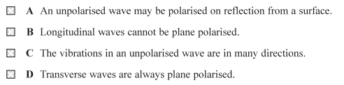
- Answer: D
- Explain:
- The statement “Transverse waves are always plane polarised” is incorrect.
- While transverse waves can be plane polarised, they are not always in that state. A transverse wave can be unpolarised, meaning its vibrations occur in many different planes perpendicular to the direction of propagation. A wave is only considered plane polarised when its vibrations are restricted to a single plane. Unpolarised transverse waves, such as light from the sun or a light bulb, can be made plane polarised by passing them through a polariser. For example, a polarising filter will only allow the components of the wave that are vibrating in a specific plane to pass through.
- 9. In an investigation to determine the Young modulus of a material in the form of a wire, a tensile force of 14 N was applied to the wire. The length of the wire was 2.0 m.
- The diameter of the wire was 2.5 mm. The length of the wire increased by 0.20%.
- (a)Calculate the Young modulus of the material.
- Explain:
- – Tensile force, [math]F=14\ \text{N}[/math]
- – Original length, [math]L=2.0\ \text{m}[/math]
- – Diameter, [math]d=2.5\ \text{mm}=2.5\times10^{-3}\ \text{m}[/math]
- – Percentage increase in length, [math]0.20\%[/math]
- – Calculate the Young modulus of the material = [math]E=?[/math]
- The cross – sectional area (A) of a circular wire is given by the formula
- [math]A=\pi r^{2}[/math]
- [math]A=\pi\left(\dfrac{d}{2}\right)^{2}[/math]
- [math]A=(3.14)\left(\dfrac{2.5\times10^{-3}}{2}\right)^{2}[/math]
- [math]A=4.9\times10^{-6}\ \text{m}^{2}[/math]
- Stress is defined as force per unit area
- [math]\sigma=\dfrac{F}{A}[/math]
- [math]\sigma=\dfrac{14}{4.9\times10^{-6} }[/math]
- [math]\sigma=2.85\times10^{6}\ \text{Pa}[/math]
- Strain ([math]\varepsilon[/math]) is the fractional change in length. The problem states the length increased by 0.2%.
- [math]\varepsilon=\dfrac{\Delta L}{L}[/math]
- [math]\varepsilon=\dfrac{0.2}{100}[/math]
- [math]\varepsilon=0.002[/math]
- [math]\varepsilon=0.2\%[/math]
- Calculate the Young modulus:
- [math]E=\dfrac{\sigma}{\varepsilon}[/math]
- [math]E=\dfrac{2.85\times10^{6}}{0.002}[/math]
- [math]E=1.43\times10^{9}\ \text{Pa}[/math]
- (b)Calculate the energy stored in the stretched wire. (2)
- Explain:
- – The change in length = [math]\Delta L=0.002\times2[/math]
- [math]\Delta L=0.004\ \text{m}[/math]
- – Calculate the energy:
- [math]U=\dfrac{1}{2}F\Delta L[/math]
- [math]U=\dfrac{1}{2}(14)(0.004)[/math]
- [math]U=7\times0.004[/math]
- [math]U=0028\ \text{J}[/math]
- (c) Explain why the wire chosen should be as long as possible. (2)
- Explain:
- – Analyze the relationship between extension and length:
- From the Young’s modulus formula, we can rearrange to find the extension:
- [math]\Delta L=\dfrac{FL}{AE}[/math]
- This equation shows that the extension ([math]\Delta L[/math]) is directly proportional to the original length of the wire.
- By choosing a longer wire, the extension ([math]\Delta L[/math]) for a given force becomes larger. A larger extension is easier to measure with a smaller percentage uncertainty. This leads to a more accurate and reliable value for the Young’s modulus.
- 10. A student investigated how a converging lens can be used to project a magnified image onto a whiteboard.
- In a darkened room, the student placed a smartphone 9.0 cm from the converging lens. The phone’s display was projected onto the whiteboard. The converging lens was 75.0 cm from the whiteboard when a clear image was produced.
- (a) Calculate the focal length of the lens.
- – Object distance = [math]9.00\ \text{cm}[/math]
- – Image distance = [math]75.0\ \text{cm}[/math]
- – Focal length = [math]f=?[/math]
- [math]\dfrac{1}{f}=\dfrac{1}{v}+\dfrac{1}{u}[/math]
- [math]\dfrac{1}{f}=\dfrac{1}{75}+\dfrac{1}{9}[/math]
- [math]\dfrac{1}{f}=\dfrac{3+25}{225}[/math]
- [math]\dfrac{1}{f}=\dfrac{28}{225}[/math]
- [math]f=\dfrac{225}{28}[/math]
- [math]f=8.04\ \text{cm}[/math]
- [math]f=8.04\times10^{-2}\ \text{m}[/math]
- (b) The image projected onto the whiteboard was real.
- State what is meant by a real image.
- Explain:
- Based on the search results, a real image is formed when light rays from an object actually converge at a point after passing through a lens or reflecting off a mirror.
- Because the light rays physically meet, a real image can be projected onto a surface, such as a screen or a wall. Real images are typically inverted (upside down) and can be either magnified or diminished in size, depending on the optical system. Examples of real images include the picture on a movie screen or the image formed on a camera’s sensor.
- (c) The display on the phone contained two dots that were 5.0 mm apart. The student stood 4.5 m from the whiteboard and viewed the image of the dots.
- Rays of light from the images of the two dots on the whiteboard were incident at the student’s eye with an angle [math]\theta[/math] between them as shown.
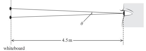
- The student could distinguish the two dots if the angle [math]\theta[/math] was greater than [math]0.0003\ \text{radians}[/math].
- Deduce whether the student could distinguish the two dots clearly.
- Explain:
- – Distance between two dots on the whiteboard = [math]5.0\ \text{mm}=5.0\times10^{-3}\ \text{m}[/math]
- – Distance from the student’s eye to the whiteboard = [math]4.5\ \text{m}[/math]
- – Minimum angle of resolution for the student’s eye: [math]\theta_{\min}=0.0003\ \text{radians}[/math]
- – The angle [math]\theta[/math] is subtended at the student’s eye by the two dots = ?
- [math]\tan(\theta/2)=\theta/2[/math]
- [math]\tan(\theta/2)=\dfrac{\text{opposite}}{\text{adjacent}}=\dfrac{d/2}{D}[/math]
- [math]\theta/2=\dfrac{d/2}{D}[/math]
- [math]\theta=\dfrac{d}{D}[/math]
- [math]\theta=\dfrac{5.0\times10^{-3}}{4.5}[/math]
- [math]\theta=0.001111\ \text{radians}[/math]
- Compare the calculated angle [math]\theta[/math] with the minimum angle required to distinguish the dots, [math]\theta_{\min}[/math]
- [math]\theta_{\min}=0.0003\ \text{radians}[/math]
- [math]\theta=0.0011\ \text{radians}[/math]
- Since [math]0.0011>0.0003[/math], the angle subtended at the student’s eye is greater than the minimum angle of resolution.
- 11. The photograph shows a guitar. The strings of the guitar are at the same tension.
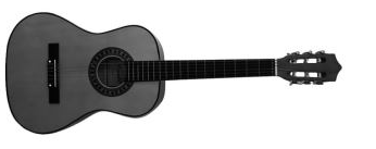
- When a string is plucked, a standing wave is set up on the string.
- (a) Explain how a standing wave is set up on a string.
- Explain:
- A standing wave is formed on a string when two identical waves, with the same frequency and amplitude, travel in opposite directions and interfere with each other. On a guitar string, plucking the string creates a transverse wave that travels along its length. This wave is reflected when it reaches the fixed ends of the string, such as the nut and the bridge.
- The reflected wave travels back along the string, interfering with new waves created by the initial pluck. This superposition of the incident and reflected waves, traveling in opposite directions, creates an interference pattern that appears to be stationary, hence the name “standing wave”.
- The points on the string that do not move are called nodes, which occur where the waves interfere destructively. The points of maximum oscillation are called antinodes, which occur where the waves interfere constructively. The presence of fixed ends on the string ensures that there are always nodes at both ends, which limits the possible frequencies that can form a standing wave. These specific frequencies are known as the string’s natural frequencies or harmonics.
- (b) A thicker string produces a note with a lower fundamental frequency than a thinner string of the same material.
- Justify this statement.
- Explain:
- State the formula for the fundamental frequency of a vibrating string:
- The fundamental frequency ([math]f[/math]) of a vibrating string is given by the formula:
- [math]f=\dfrac{v}{2L}[/math]
- Where [math]v[/math] is the speed of the wave on the string and [math]L[/math] is the length of the string.
- Relate wave speed to string properties:
- The speed of a wave ([math]v[/math]) on a string is determined by the tension ([math]T[/math]) and the linear mass density ([math]\mu[/math]) of the string. The formula for wave speed is:
- [math]v=\sqrt{\dfrac{T}{\mu}}[/math]
- Linear mass density ([math]\mu[/math]) is the mass per unit length of the string, which can be expressed as
- [math]\mu=\dfrac{m}{L}[/math]
- For a cylindrical string, the mass ([math]m[/math]) is its volume multiplied by its density ([math]\rho[/math]),
- So
- [math]m=\pi r^{2}L\rho[/math]
- Where [math]r[/math] is the radius of the string.
- Substituting this into the linear mass density formula gives:
- [math]\mu=\dfrac{\pi r^{2}L\rho}{L}[/math]
- [math]\mu=\pi r^{2}\rho[/math]
- Since the problem states the strings are of the same material, the density [math]\rho[/math] is constant. A thicker string has a larger radius ([math]r[/math]) which means it has a greater linear mass density ([math]\mu[/math]).
- Combine the formulas to show the relationship:
- Substituting the expression for wave speed into the fundamental frequency formula gives:
- [math]f=\dfrac{1}{2L}\sqrt{\dfrac{T}{\mu}}[/math]
- Since the strings are made of the same material and are assumed to be under the same tension and have the same length, the only variable that changes is the linear mass density ([math]\mu[/math]).
- From the formula, the fundamental frequency ([math]f[/math]) is inversely proportional to the square root of the linear mass density ([math]\mu[/math]).
- [math]f\propto\dfrac{1}{\sqrt{\mu}}[/math]
- Therefore, a larger linear mass density ([math]\mu[/math]) results in a lower fundamental frequency ([math]f[/math]).
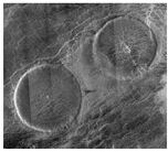
- 12. The photograph shows an image of two “pancake” volcanoes on the surface of the planet Venus. Scientists believe these types of volcano are formed from lava spreading out in all directions onto a flat landscape.
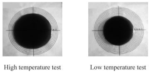
- A student investigated the formation of pancake volcanoes. She observed the flow of a viscous liquid at two different temperatures as it spread out from a central spot. The photographs below show the liquid at both temperatures after it had been flowing for the same length of time.
- (a) Scientists believe that the high temperature of lava when it erupts is one factor that allows the lava to spread out over a large area.
- Explain how the student’s investigation supports this idea.
- Explain:
- The student’s investigation supports the idea that high temperature allows lava to spread over a large area.
- – The “High temperature test” shows the viscous liquid spreading out to a much larger radius compared to the “Low temperature test.”
- – Since both tests ran for the same length of time, the results indicate that a higher temperature allows the liquid to flow more easily and cover a greater area.
- – This directly models the behavior of lava: at a higher temperature, lava is less viscous and can spread out over a larger, flatter area, forming a pancake volcano.
- The student’s investigation supports the idea that high-temperature lava spreads out over a large area because the liquid in the “High temperature test” spread out into a much larger circle than the liquid in the “Low temperature test” after the same amount of time.
- This demonstrates that a higher temperature reduces the viscosity of the liquid, allowing it to flow more easily and spread over a greater distance. This directly models how the high temperature of lava would allow it to spread out to form a “pancake” volcano, as opposed to a more conical volcano formed by more viscous, cooler lava.
- The photograph for the high-temperature test shows the viscous liquid spreading out to cover a much larger area compared to the low-temperature test. The liquid in the low-temperature test did not spread as far from the central point.
- (b) The student carried out an experiment to determine the viscosity of the liquid at room temperature. She observed a steel sphere falling through the liquid.
- She had the following equipment:
- – A long, wide cylindrical tube
- – Two steel spheres with diameters 7.0 mm and 22.0 mm
- – Video camera
- – Meter rule
- The student observed the sphere with a diameter of 7.0 mm falling through the liquid. The sphere fell 0.80 m in 5.3 s at a constant velocity.
- The viscosity n of the liquid can be calculated using the equation
- [math]\mu=\dfrac{Vg(\rho_s-\rho_l)}{6\pi r\nu}[/math]
- Providing Stokes law applies.
- (i) Calculate the viscosity of the liquid.
- – density of liquid [math]\rho_l=1430\ \text{kg m}[/math]
- – density of steel [math]\rho_s=7800\ \text{kg m}[/math]
- Explain:
- – The sphere fell a distance = [math]s=0.80\ \text{m}[/math]
- – Time = [math]t=5.3\ \text{s}[/math]
- – Density of liquid [math]\rho_l=1430\ \text{kg m}[/math]
- – Density of steel [math]\rho_s=7800\ \text{kg m}[/math]
- – Radius of the sphere = [math]r=3.5\ \text{mm}=3.5\times10^{-3}\ \text{m}[/math]
- – Calculate the viscosity of the liquid.
- [math]v=\dfrac{s}{t}[/math]
- [math]v=\dfrac{0.80}{5.3}[/math]
- [math]v=0.15\ \text{m s}^{-1}[/math]
- [math]\mu=\dfrac{Vg(\rho_s-\rho_l)}{6\pi r\nu}[/math]
- [math]V=\dfrac{4}{3}\pi r^{3}[/math]
- [math]\mu=\dfrac{(4/3)\pi r^{3}g(\rho_s-\rho_l)}{6\pi r\nu}[/math]
- [math]\mu=\dfrac{4r^{2}g(\rho_s-\rho_l)}{18\nu}[/math]
- [math]\mu=\dfrac{2r^{2}g(\rho_s-\rho_l)}{9\nu}[/math]
- [math]\mu=\dfrac{2(3.5\times10^{-3})^{2}(9.8)(7800-1430)}{9(0.15)}[/math]
- [math]\mu=\dfrac{2(1.225\times10^{-5})(9.8)(6370)}{1.358}[/math]
- [math]\mu=\dfrac{1.532}{1.358}[/math]
- [math]\mu=1.1\ \text{Pa s}[/math]
- (ii) If the student had used the larger sphere, the equation would not have produced the correct answer.
- Explain why.
- Explain:
- The answer is based on the principle of the surface area-to-volume ratio.
- As a sphere’s size increases, its volume increases at a faster rate than its surface area. The volume of a sphere is proportional to the cube of its radius
- [math]V\propto r^{3}[/math]
- while its surface area is proportional to the square of its radius
- [math]A\propto r^{2}[/math]
- Therefore, the ratio of surface area to volume decreases as the sphere gets larger. The specific equation or experiment being referenced likely relies on a correct balance between the surface area and volume of the sphere.
- Using a larger sphere would alter this ratio, and if the equation doesn’t account for this change, it would produce an incorrect result. For example, if a process depends on a reaction occurring on the surface of the sphere, a larger sphere would have a smaller surface area relative to its volume, which would change the overall outcome of the reaction.
- (iii) The student used the video camera to record the sphere falling through the liquid.
- State one benefit of using the video camera to record the motion of the sphere.
- Explain:
- One benefit of using a video camera is that it allows for the motion of the sphere to be analyzed frame-by-frame, which provides a more detailed and accurate measurement of its position and velocity over time. This can be particularly useful for analyzing fast movements or for observing the motion in slow-motion to see details that would be difficult to observe with the naked eye.
- 13. The diffraction of light provides evidence for the wave theory of light.
- (a) The diagram represents wavefronts of light, incident at a single slit. The points labelled A, B and C are points on the wavefront that has just passed through the gap.
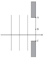
- (i) Describe what is meant by a wavefront.
- Explain:
- A wavefront is an imaginary surface that connects all points of a wave that are in the same phase of oscillation. The wavefront represents the leading edge of a wave as it travels through a medium, and it is always perpendicular to the direction of wave propagation (the ray).
- The shape of the wavefront depends on the source of the wave. For a point source, the wavefronts are spherical surfaces expanding outwards. For a distant source, a small section of a spherical wavefront appears flat, creating a plane wavefront. The propagation of wavefronts is explained by Huygens’ principle, which states that every point on a wavefront acts as a source of secondary wavelets, and the new wavefront is the tangent to all of these wavelets.
- (ii) Add to the diagram to show how Huygens’ construction can be used to determine the shape of the next wavefront, after the wave has passed through the gap. (3)
- Explain:
- – Apply Huygens’ principle
- Huygens’ principle states that every point on a wavefront can be considered a source of secondary spherical wavelets. The provided diagram shows a plane wavefront incident on a single slit. The points A, B, and C are on the wavefront that has just passed through the gap and act as sources for these secondary wavelets.
- – Draw secondary wavelets
- According to Huygens’ principle, each point on a wavefront acts as a source of secondary spherical wavelets. From points A, B, and C, draw three circular arcs (wavelets) of the same radius, representing the distance the wave has traveled in a short time interval.
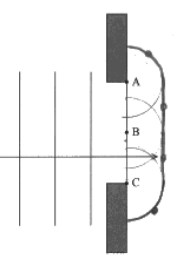
- – Construct the new wavefront
- The new wavefront is the envelope or tangent to all the secondary wavelets. Draw a curved line that is tangential to the three circular arcs, forming the new wavefront.
- (b) A student carried out an investigation to determine the wavelength of the light emitted from a laser pen.
- He shone the light from the laser pen so that it was incident perpendicularly on a diffraction grating. The diffraction grating had 200 lines per mm. He observed the diffraction pattern on a screen 3.00 m away from the grating. The pattern consisted of a series of bright dots.

- (i) Give a reason why a laser is a suitable source of light to produce a diffraction pattern.
- Explain:
- A laser is a suitable source of light because it is both monochromatic and coherent.
- – Monochromatic:
- A laser produces light of a single wavelength (or color). This is crucial for a diffraction experiment because it results in a clear, sharp, and well-defined diffraction pattern with distinct bright spots that are easy to measure.
- Using a source with multiple wavelengths, like white light, would produce a series of overlapping spectra, making the pattern blurry and difficult to analyze.
- – Coherent:
- The light waves from a laser are in phase with one another. This spatial and temporal coherence is essential for creating a stable and high-contrast interference pattern.
- The bright spots in the pattern are a result of constructive interference, which is maximized when the light waves are coherent.
- (ii) The student measured a distance of 102 cm between the central maximum and the centre of a third order maximum.
- The table shows the range of wavelengths for each colour of the visible spectrum.
-
Colour Range of wavelength (nm) Violet 380 – 450 Blue 450 – 495 Green 495 – 570 Yellow 570 – 590 Orange 590 – 620 Red 620 – 750 - Deduce the colour of the light emitted from the laser pen.
- Explain:
- – The number of lines per unit length = 200 lines per mm
- – The distance from the grating to the screen = [math]L=3.00\ \text{m}[/math]
- – The distance from the central maximum to the third-order maximum = [math]x=102\ \text{cm}=1.02\ \text{m}[/math]
- – Calculate the wavelength = [math]\lambda=?[/math]
- – The diffraction grating spacing = [math]d=?[/math]
- [math]d=\frac{1}{\text{number of lines per mm}}[/math]
- [math]d=\dfrac{1}{200\ \text{mm}}[/math]
- [math]d=5\times10^{-6}\ \text{m}[/math]
- Using the trigonometry:
- [math]\tan\theta=\dfrac{x}{L}[/math]
- [math]\tan\theta=\dfrac{1.02}{3.00}[/math]
- [math]\tan\theta=0.34[/math]
- [math]\theta=\tan^{-1}(0.34)[/math]
- [math]\theta=18.78^{\circ}[/math]
- Using the diffraction grating equation:
- – [math]n=3[/math]
- [math]n\lambda=d\sin\theta[/math]
- [math]3\lambda=(5\times10^{-6})\sin(18.78^\circ)[/math]
- [math]\lambda=\dfrac{(5\times10^{-6})(0.322)}{3}[/math]
- [math]\lambda=5.37\times10^{-7}\ \text{m}[/math]
- [math]\lambda=537\times10^{-9}\ \text{m}[/math]
- [math]\lambda=537\ \text{nm}[/math]
- Deduce the colour
- – The calculated wavelength is [math]537\ \text{nm}[/math]
- – The provided table shows that the range of wavelengths for green light is 495 – 570 nm.
- – Since 537 nm falls within this range, the colour of the laser light is green.
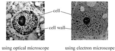
- 14. An optical microscope uses a beam of visible light. An electron microscope uses a beam of electrons.
- A biologist looked at an animal cell using both microscopes. The two images are shown; both have the same magnification.
- (a) An electron in the beam of the electron microscope has a velocity of 2% of the speed of light.
- Calculate the de Broglie wavelength of the electron.
- Explain:
- – Planck’s Constant, [math]h=6.626\times10^{-34}\ \text{J s}[/math]
- – Mass of an electron, [math]m=9.1\times10^{-31}\ \text{kg}[/math]
- – Speed of light, [math]c=3\times10^{8}\ \text{m s}^{-1}[/math]
- – Calculate the de Broglie wavelength of the electron = [math]\lambda=?[/math]
- The problem states that the electron’s velocity is 2% of the speed of light.
- [math]v=0.02c[/math]
- [math]v=0.02\times3\times10^{8}[/math]
- [math]v=5.9\times10^{6}\ \text{m s}^{-1}[/math]
- [math]\lambda=\dfrac{h}{mv}[/math]
- [math]\lambda=\dfrac{6.626\times10^{-34}}{(9.1\times10^{-31})(3\times10^{8})}[/math]
- [math]\lambda=\dfrac{6.626\times10^{-34}}{5.4\times10^{-24}}[/math]
- [math]\lambda\approx1.2\times10^{-10}\ \text{m}[/math]
- (b) The image of the animal cell produced by the electron microscope is less blurred than the image produced by the optical microscope.
- Explain why.
- Explain:
- The resolution of a microscope, which determines how clear and detailed an image is, is inversely proportional to the wavelength of the radiation used.
- – An optical microscope uses visible light, which has a longer wavelength (400–700 nm).
- – An electron microscope uses a beam of electrons, which have a much shorter de Broglie wavelength than visible light.
- Since the wavelength of the electron beam is significantly shorter than the wavelength of visible light, the electron microscope has a much higher resolving power. This allows it to distinguish between objects that are closer together, resulting in a clearer, less blurred image with greater detail.
- (c) The biologist measured the diameter of the cell from one of the images. He recorded four measurements. The image had a magnification of ×800
-
Diameter of Image / cm 2.4 2.5 1.1 2.2 - Determine a value for the diameter of the actual cell.
- Explain:
- – Calculate the diameter of the image
- Average diameter of image= [math]\dfrac{2.4+2.5+1.1+2.2}{4}[/math]
- Average diameter of image= [math]\dfrac{8.2}{4}[/math]
- Average diameter of image= [math]2.05\ \text{cm}[/math]
- – Use the magnification formula:
- [math]\text{Magnification}=\dfrac{\text{Image Size}}{\text{Actual Size}}[/math]
- [math]\text{Magnification}=\dfrac{2.05}{800}[/math]
- [math]\text{Magnification}=0.00256\ \text{cm}[/math]
- [math]\text{Magnification}=0.003\ \text{cm}[/math]
- [math]\text{Magnification}=0.00003\ \text{m}[/math]
- [math]\text{Magnification}=3\times10^{-5}\ \text{m}[/math]
-
SECTION B
-
Answers All Questions
- 15. Read the passage and answer the questions below.
-
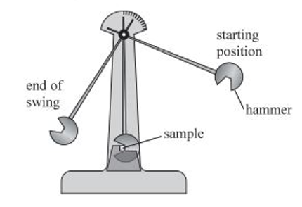
- (ref: Physics Review April 2015 p22)
- The Charpy test is used by scientists to measure the fracture toughness of a material. A simple pendulum, with a hammer on the end, is held high and released so that it swings down and strikes the sample. The height from which the hammer is released is increased until the sample fractures.
- Some energy is absorbed by the sample in the impact but the hammer continues to move until it comes to rest at the top of its swing. Due to the law of conservation of energy the hammer will not swing up as high as its starting position. The difference in height between the start and end is proportional to the energy absorbed in the impact-the fracture toughness.
- (a) “The difference in height between the start and end is proportional to the energy absorbed in the impact the fracture toughness.”
- Justify this statement.
- Explain:
- The statement is justified by the principle of conservation of energy.
- The potential energy (PE) of the hammer at a certain height (h) is given by the formula
- [math]PE=mgh[/math]
- Where m is the mass of the hammer and g is the acceleration due to gravity.
- – The initial potential energy of the hammer is
- [math]\text{PE}_{\text{initial}}=mgh_{\text{initial}}[/math]
- – The final potential energy of the hammer after breaking the sample is
- [math]\text{PE}_{\text{final}}=mgh_{\text{final}}[/math]
- According to the law of conservation of energy, the total energy of the system is constant. In the Charpy test, the energy absorbed by the sample [math]E_{\text{absorbed}}[/math] is the difference between the initial potential energy and the final potential energy of the hammer, assuming energy losses due to friction are negligible.
- This relationship can be expressed as:
- [math]E_{\text{absorbed}}=\text{PE}_{\text{initial}}-\text{PE}_{\text{final}}[/math]
- [math]E_{\text{absorbed}}=mgh_{\text{initial}}-mgh_{\text{final}}[/math]
- [math]E_{\text{absorbed}}=mg(h_{\text{initial}}-h_{\text{final}})[/math]
- Since the mass of the hammer (m) and the acceleration due to gravity (g) are constants, the absorbed energy [math]E_{\text{absorbed}}[/math] is directly proportional to the difference in height
- [math]\Delta h=h_{\text{initial}}-h_{\text{final}}[/math]
- This difference in absorbed energy is what is measured as fracture toughness.
- (b) The hammer is released from a height of 13.0 cm above the lowest point of the swing.
- Calculate the momentum of the hammer when it strikes the sample. mass of hammer = 31 kg (3)
- – Height = h = 13 cm = 0.13 m
- – Mass = m = 31 kg
- – Calculate the momentum of the hammer = p = ?
- [math]PE=mgh[/math]
- [math]KE=\frac{1}{2}mv^2[/math]
- We assume that all potential energy is converted to kinetic energy
- [math]PE=KE[/math]
- [math]mgh=\frac{1}{2}mv^2[/math]
- [math]gh=\frac{1}{2}v^2[/math]
- [math]\sqrt{v^2}=\sqrt{2gh}[/math]
- [math]v=\sqrt{2gh}[/math]
- Putting the values
- [math]v=\sqrt{2(9.8)(0.13)}[/math]
- [math]v=\sqrt{2.5506}[/math]
- [math]v=1.597\ \text{m/s}[/math]
- [math]p=mv[/math]
- [math]p=(31)(1.597)[/math]
- [math]p=49.5\ \text{kg.m/s}[/math]
- [math]p=50\ \text{kg.m/s}[/math]
- (c) The sketch graph shows how the fracture toughness of a sample of steel varies with temperature.
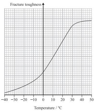
- A material with a low fracture toughness can absorb less energy before fracture than a material with high fracture toughness.
- The ship Titanic sank in 1912 following a collision with an iceberg in the icy waters of the Atlantic. The steel hull of the ship was fractured by the impact.
- Deduce why the steel was likely to have been fractured by the impact.
- Explain:
- The steel of the Titanic’s hull was likely fractured because its fracture toughness was significantly reduced by the low temperature of the icy water.
- Analyze the graph:
- – The provided graph shows that as the temperature decreases, the fracture toughness of the steel also decreases. The graph has a steep drop in fracture toughness as the temperature falls below 100C and continues to decrease as the temperature approaches 400C.
- Relate fracture toughness to the material’s properties:
- – The text states that a material with low fracture toughness can absorb less energy before fracturing.
- Apply to the Titanic scenario:
- – The Titanic was in the “icy waters of the Atlantic,” which means the temperature of the steel hull would have been very low. According to the graph, this low temperature would have caused the steel to have a very low fracture toughness.
- Deduce the cause of the fracture:
- – With a low fracture toughness, the steel could not absorb much energy from the impact with the iceberg. This made the steel brittle and more susceptible to fracture, leading to the hull breaking upon impact.
- 16. A solar panel uses electromagnetic radiation from the Sun to generate electricity. In one installation a sensor in the solar panel measures the intensity of radiation arriving from different directions. A motor rotates the solar panel so that it always faces the brightest part of the sky.
- (a) The intensity of the radiation incident at the surface of the Earth is 1100 W m². A solar panel has an area of 2.4 m². Radiation is incident on the solar panel at an angle of 50° as shown. The efficiency of the solar panel is 20%.
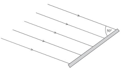
- Calculate the electrical power generated by the solar panel.
- Explain:
- – The angle of incident = [math]50^0[/math]
- – Intensity of the radiation = [math]I = 1100\ \text{W.m}^{-2}[/math]
- – The solar panel has an efficiency = 20% = [math]0.20[/math]
- – To Calculate the affective area = [math]A_{eff}=?[/math]
- – Calculate the total power incident = [math]P_{incident}=?[/math]
- – Calculate the electrical power generated = [math]P_{generated}=?[/math]
- [math]A_{eff}=A \sin 50^0[/math]
- [math]A_{eff}=2.4 \sin 50^0[/math]
- [math]A_{eff}=1.8384\ \text{m}^2[/math]
- [math]P_{incident}=I\times A_{eff}[/math]
- [math]P_{incident}=1100\times1.8384[/math]
- [math]P_{incident}=2022.24\ \text{W}[/math]
- [math]P_{generated}=\text{Efficiency}\times P_{incident}[/math]
- [math]P_{generated}=0.20\times2022.24[/math]
- [math]P_{generated}=404.45\ \text{W}[/math]
- The electrical power generated by the solar panel is approximately 400 W.
- (b) The circuit diagram shows how a light dependent resistor (LDR) can be used to produce an output potential difference (p.d.) that is dependent on the intensity of light. This output p.d. is connected to a motor circuit that operates the movement of the solar panel.
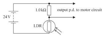
- Initially the motor is switched off. The light intensity increases and the resistance of the LDR decreases to 750 Ω.
- The motor switches on when the output p.d. is above 13 V.
- Deduce whether this change in light intensity causes the motor to switch on.
- Explain:
- – Fixed resistor [math]R_{fixed}=1.0\ \text{k}\Omega[/math]
- – The LDR resistance = [math]R_{LDR}=750\ \Omega[/math]
- – The total voltage = [math]V_{total}=24\ \text{V}[/math]
- – Calculate the total resistance = [math]R_{total}=?[/math]
- – Calculate the total current = [math]I_{total}=?[/math]
- – Calculate the total potential difference = [math]V_{out}=?[/math]
- [math]R_{total}=R_{fixed}+R_{LDR}[/math]
- [math]R_{total}=1000+750[/math]
- [math]R_{total}=1750\ \Omega[/math]
- By using Ohm’s Law
- [math]I_{total}=\frac{V_{total}}{R_{total}}[/math]
- [math]I_{total}=\frac{24}{1750}[/math]
- [math]I_{total}=0.0137\ \text{A}[/math]
- [math]V_{out}=I_{total}\times R_{fixed}[/math]
- [math]V_{out}=0.0137\times1000[/math]
- [math]V_{out}=13.7\ \text{V}[/math]
- (c) When light is incident on an LDR, electrons move to a higher energy level where they become conduction electrons. This causes the resistance of the LDR to decrease.
- A student suggests that this is an example of the photoelectric effect. The student is not correct.
- Compare and contrast the photoelectric effect with the effect of radiation incident on an LDR.
- Explain:
- Define the photoelectric effect and its characteristics
- The photoelectric effect is the emission of electrons from a metal surface when it is illuminated by electromagnetic radiation of a sufficiently high frequency. The key characteristics are:
- – Electrons are emitted from the surface of the material, not from within.
- – The emitted electrons are called photoelectrons, and they are completely freed from the material.
- – The frequency of the incident radiation must be above a certain threshold frequency, [math]f_0[/math], for electrons to be emitted, regardless of the intensity of the light.
- – The maximum kinetic energy of the emitted electrons, [math]KE_{max}[/math], depends on the frequency of the incident radiation, [math]f[/math], and the work function, [math]\phi[/math], of the metal. This relationship is given by Einstein’s photoelectric equation:
- [math]KE_{max}=hf-\phi[/math]
- Where [math]h[/math] is Planck’s Constant.
- – The number of photoelectrons emitted per second is directly proportional to the intensity of the incident radiation, provided the frequency is above the threshold frequency.
- – The effect is instantaneous; electrons are emitted as soon as the radiation hits the surface.
- Define the effect of radiation on an LDR and its characteristics
- A Light Dependent Resistor (LDR) is a semiconductor device whose resistance decreases as the intensity of incident light increases. When light (radiation) is incident on an LDR, photons are absorbed by electrons in the semiconductor material. The key characteristics are:
- – The electrons absorb energy from the photons and are excited from the valence band to the conduction band.
- – These excited electrons are not ejected from the material; they remain within the semiconductor lattice and become charge carriers (conduction electrons).
- – The increase in the number of conduction electrons and corresponding holes increases the conductivity of the material, which in turn causes the resistance of the LDR to decrease.
- – The effect depends on the intensity of the light. Higher intensity means more photons, which in turn creates more charge carriers and leads to a larger decrease in resistance.
- – The energy required to excite an electron from the valence band to the conduction band is the band gap energy [math]E_g[/math].
- Compare and contrast the two effects
- Comparison (Similarities)
- – Both effects involve electrons absorbing energy from incident electromagnetic radiation (light).
- – In both cases, the absorbed energy causes electrons to move to a higher energy state.
- Contract (Differences)
-
Feature Photoelectric Effect Effect of Radiation on DR Electron Behavior Electrons are completely ejected from the surface of the material. Electrons are excited from the valence band to the conduction band but remain within the material. Material Type Occurs in metals. Occurs in semiconductors. Energy Requirement The energy of a photon must be greater than the work function ( of the metal. The energy of a photon must be greater than the band gap energy of the semiconductor. Result Emits free electrons (photoelectrons). Increases the number of charge carriers (conduction electrons and holes) within the material. Application Used in photocells and photomultipliers. Used in light sensors and light-activated circuits.